Quantum Advantage in Learning from Experiments

In efforts to learn about the quantum world, scientists face a big obstacle: their classical experience of the world. Whenever a quantum system is measured, the act of this measurement destroys the “quantumness” of the state. For example, if the quantum state is in a superposition of two locations, where it can seem to be in two places at the same time, once it is measured, it will randomly appear either ”here” or “there”, but not both. We only ever see the classical shadows cast by this strange quantum world.

A growing number of experiments are implementing machine learning (ML) algorithms to aid in analyzing data, but these have the same limitations as the people they aim to help: They can’t directly access and learn from quantum information. But what if there were a quantum machine learning algorithm that could directly interact with this quantum data?

In “Quantum Advantage in Learning from Experiments”, a collaboration with researchers at Caltech, Harvard, Berkeley, and Microsoft published in Science, we show that a quantum learning agent can perform exponentially better than a classical learning agent at many tasks. Using Google’s quantum computer, Sycamore, we demonstrate the tremendous advantage that a quantum machine learning (QML) algorithm has over the best possible classical algorithm. Unlike previous quantum advantage demonstrations, no advances in classical computing power could overcome this gap. This is the first demonstration of a provable exponential advantage in learning about quantum systems that is robust even on today’s noisy hardware.

Quantum Speedup
QML combines the best of both quantum computing and the lesser-known field of quantum sensing.

Quantum computers will likely offer exponential improvements over classical systems for certain problems, but to realize their potential, researchers first need to scale up the number of qubits and to improve quantum error correction. What’s more, the exponential speed-up over classical algorithms promised by quantum computers relies on a big, unproven assumption about so-called “complexity classes” of problems — namely, that the class of problems that can be solved on a quantum computer is larger than those that can be solved on a classical computer.. It seems like a reasonable assumption, and yet, no one has proven it. Until it’s proven, every claim of quantum advantage will come with an asterisk: that it can do better than any known classical algorithm.

Quantum sensors, on the other hand, are already being used for some high-precision measurements and offer modest (and proven) advantages over classical sensors. Some quantum sensors work by exploiting quantum correlations between particles to extract more information about a system than it otherwise could have. For example, scientists can use a collection of N atoms to measure aspects of the atoms’ environment like the surrounding magnetic fields. Typically the sensitivity to the field that the atoms can measure scales with the square root of N. But if one uses quantum entanglement to create a complex web of correlations between the atoms, then one can improve the scaling to be proportional to N. But as with most quantum sensing protocols, this quadratic speed-up over classical sensors is the best one can ever do.

Enter QML, a technology that straddles the line between quantum computers and quantum sensors. QML algorithms make computations that are aided by quantum data. Instead of measuring the quantum state, a quantum computer can store quantum data and implement a QML algorithm to process the data without collapsing it. And when this data is limited, a QML algorithm can squeeze exponentially more information out of each piece it receives when considering particular tasks.

Comparison of a classical machine learning algorithm and a quantum machine learning algorithm. The classical machine learning algorithm measures a quantum system, then performs classical computations on the classical data it acquires to learn about the system. The quantum machine learning algorithm, on the other hand, interacts with the quantum states produced by the system, giving it a quantum advantage over the CML.

To see how a QML algorithm works, it’s useful to contrast with a standard quantum experiment. If a scientist wants to learn about a quantum system, they might send in a quantum probe, such as an atom or other quantum object whose state is sensitive to the system of interest, let it interact with the system, then measure the probe. They can then design new experiments or make predictions based on the outcome of the measurements. Classical machine learning (CML) algorithms follow the same process using an ML model, but the operating principle is the same — it’s a classical device processing classical information.

A QML algorithm instead uses an artificial “quantum learner.” After the quantum learner sends in a probe to interact with the system, it can choose to store the quantum state rather than measure it. Herein lies the power of QML. It can collect multiple copies of these quantum probes, then entangle them to learn more about the system faster.

Suppose, for example, the system of interest produces a quantum superposition state probabilistically by sampling from some distribution of possible states. Each state is composed of n quantum bits, or qubits, where each is a superposition of “0” and “1” — all learners are allowed to know the generic form of the state, but must learn its details.

In a standard experiment, where only classical data is accessible, every measurement provides a snapshot of the distribution of quantum states, but since it’s only a sample, it is necessary to measure many copies of the state to reconstruct it. In fact, it will take on the order of 2n copies.

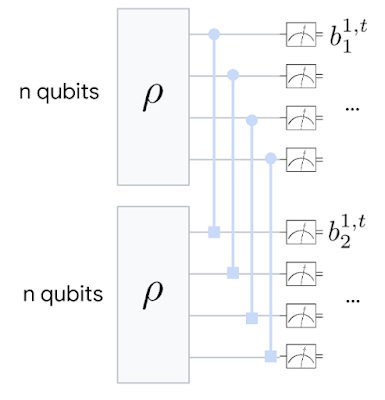
A QML agent is more clever. By saving a copy of the n-qubit state, then entangling it with the next copy that comes along, it can learn about the global quantum state more quickly, giving a better idea of what the state looks like sooner.

Basic schematic of the QML algorithm. Two copies of a quantum state are saved, then a “Bell measurement” is performed, where each pair is entangled and their correlations measured.

<!–

Basic schematic of the QML algorithm. Two copies of a quantum state are saved, then a “Bell measurement” is performed, where each pair is entangled and their correlations measured.

–>

The classical reconstruction is like trying to find an image hiding in a sea of noisy pixels — it could take a very long time to average-out all the noise to know what the image is representing. The quantum reconstruction, on the other hand, uses quantum mechanics to isolate the true image faster by looking for correlations between two different images at once.

Results
To better understand the power of QML, we first looked at three different learning tasks and theoretically proved that in each case, the quantum learning agent would do exponentially better than the classical learning agent. Each task was related to the example given above:

  1. Learning about incompatible observables of the quantum state — i.e., observables that cannot be simultaneously known to arbitrary precision due to the Heisenberg uncertainty principle, like position and momentum. But we showed that this limit can be overcome by entangling multiple copies of a state.
  2. Learning about the dominant components of the quantum state. When noise is present, it can disturb the quantum state. But typically the “principal component” — the part of the superposition with the highest probability — is robust to this noise, so we can still glean information about the original state by finding this dominant part.
  3. Learning about a physical process that acts on a quantum system or probe. Sometimes the state itself is not the object of interest, but a physical process that evolves this state is. We can learn about various fields and interactions by analyzing the evolution of a state over time.

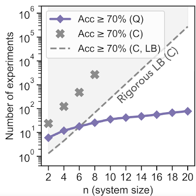
In addition to the theoretical work, we ran some proof-of-principle experiments on the Sycamore quantum processor. We started by implementing a QML algorithm to perform the first task. We fed an unknown quantum mixed state to the algorithm, then asked which of two observables of the state was larger. After training the neural network with simulation data, we found that the quantum learning agent needed exponentially fewer experiments to reach a prediction accuracy of 70% — equating to 10,000 times fewer measurements when the system size was 20 qubits. The total number of qubits used was 40 since two copies were stored at once.

Experimental comparison of QML vs. CML algorithms for predicting a quantum state’s observables. While the number of experiments needed to achieve 70% accuracy with a CML algorithm (“C” above) grows exponentially with the size of the quantum state n, the number of experiments the QML algorithm (“Q”) needs is only linear in n. The dashed line labeled “Rigorous LB (C)” represents the theoretical lower bound (LB) — the best possible performance — of a classical machine learning algorithm.

<!–

Experimental comparison of QML vs. CML algorithms for predicting a quantum state’s observables. While the number of experiments needed to achieve 70% accuracy with a CML algorithm (“C” above) grows exponentially with the size of the quantum state n, the number of experiments the QML algorithm (“Q”) needs is only linear in n. The dashed line labeled “Rigorous LB (C)” represents the theoretical lower bound (LB) — the best possible performance — of a classical machine learning algorithm.

–>

In a second experiment, relating to the task 3 above, we had the algorithm learn about the symmetry of an operator that evolves the quantum state of their qubits. In particular, if a quantum state might undergo evolution that is either totally random or random but also time-reversal symmetric, it can be difficult for a classical learner to tell the difference. In this task, the QML algorithm can separate the operators into two distinct categories, representing two different symmetry classes, while the CML algorithm fails outright. The QML algorithm was completely unsupervised, so this gives us hope that the approach could be used to discover new phenomena without needing to know the right answer beforehand.

Experimental comparison of QML vs. CML algorithms for predicting the symmetry class of an operator. While QML successfully separates the two symmetry classes, the CML fails to accomplish the task.

Conclusion
This experimental work represents the first demonstrated exponential advantage in quantum machine learning. And, distinct from a computational advantage, when limiting the number of samples from the quantum state, this type of quantum learning advantage cannot be challenged, even by unlimited classical computing resources.

So far, the technique has only been used in a contrived, “proof-of-principle” experiment, where the quantum state is deliberately produced and the researchers pretend not to know what it is. To use these techniques to make quantum-enhanced measurements in a real experiment, we’ll first need to work on current quantum sensor technology and methods to faithfully transfer quantum states to a quantum computer. But the fact that today’s quantum computers can already process this information to squeeze out an exponential advantage in learning bodes well for the future of quantum machine learning.

Acknowledgements
We would like to thank our Quantum Science Communicator Katherine McCormick for writing this blog post. Images reprinted with permission from Huang et al., Science, Vol 376:1182 (2022).

Read More

Mapping Urban Trees Across North America with the Auto Arborist Dataset

Over four billion people live in cities around the globe, and while most people interact daily with others — at the grocery store, on public transit, at work — they may take for granted their frequent interactions with the diverse plants and animals that comprise fragile urban ecosystems. Trees in cities, called urban forests, provide critical benefits for public health and wellbeing and will prove integral to urban climate adaptation. They filter air and water, capture stormwater runoff, sequester atmospheric carbon dioxide, and limit erosion and drought. Shade from urban trees reduces energy-expensive cooling costs and mitigates urban heat islands. In the US alone, urban forests cover 127M acres and produce ecosystem services valued at $18 billion. But as the climate changes these ecosystems are increasingly under threat.

Census data is typically not comprehensive, covering a subset of public trees and not including those in parks.

Urban forest monitoring — measuring the size, health, and species distribution of trees in cities over time — allows researchers and policymakers to (1) quantify ecosystem services, including air quality improvement, carbon sequestration, and benefits to public health; (2) track damage from extreme weather events; and (3) target planting to improve robustness to climate change, disease and infestation.

However, many cities lack even basic data about the location and species of their trees. Collecting such data via a tree census is costly (a recent Los Angeles census cost $2 million and took 18 months) and thus is typically conducted only by cities with substantial resources. Further, lack of access to urban greenery is a key aspect of urban social inequality, including socioeconomic and racial inequality. Urban forest monitoring enables the quantification of this inequality and the pursuit of its improvement, a key aspect of the environmental justice movement. But machine learning could dramatically lower tree census costs using a combination of street-level and aerial imagery. Such an automated system could democratize access to urban forest monitoring, especially for under-resourced cities that are already disproportionately affected by climate change. While there have been prior efforts to develop automated urban tree species recognition from aerial or street-level imagery, a major limitation has been a lack of large-scale labeled datasets.

Today we introduce the Auto Arborist Dataset, a multiview urban tree classification dataset that, at ~2.6 million trees and >320 genera, is two orders of magnitude larger than those in prior work. To build the dataset, we pulled from public tree censuses from 23 North American cities (shown above) and merged these records with Street View and overhead RGB imagery. As the first urban forest dataset to cover multiple cities, we analyze in detail how forest models can generalize with respect to geographic distribution shifts, crucial to building systems that scale. We are releasing all 2.6M tree records publicly, along with aerial and ground-level imagery for 1M trees.

The 23 cities in the dataset are spread across North America, and are categorized into West, Central, and East regions to enable analysis of spatial and hierarchical generalization.
The number of tree records and genera in the dataset, per city and per region. The holdout city (which is never seen during training in any capacity) for each region is in bold.

The Auto Arborist Dataset
To curate Auto Arborist, we started from existing tree censuses which are provided by many cities online. For each tree census considered, we verified that the data contained GPS locations and genus/species labels, and was available for public use. We then parsed these data into a common format, fixing common data entry errors (such as flipped latitude/longitude) and mapping ground-truth genus names (and their common misspellings or alternate names) to a unified taxonomy. We have chosen to focus on genus prediction (instead of species-level prediction) as our primary task to avoid taxonomic complexity arising from hybrid and subspecies and the fact that there is more universal consensus on genus names than species names.

Next, using the provided geolocation for each tree, we queried an RGB aerial image centered on the tree and all street-level images taken within 2-10 meters around it. Finally, we filtered these images to (1) maximize our chances that the tree of interest is visible from each image and (2) preserve user privacy. This latter concern involved a number of steps including the removal of images that included people as determined by semantic segmentation and manual blurring, among others.

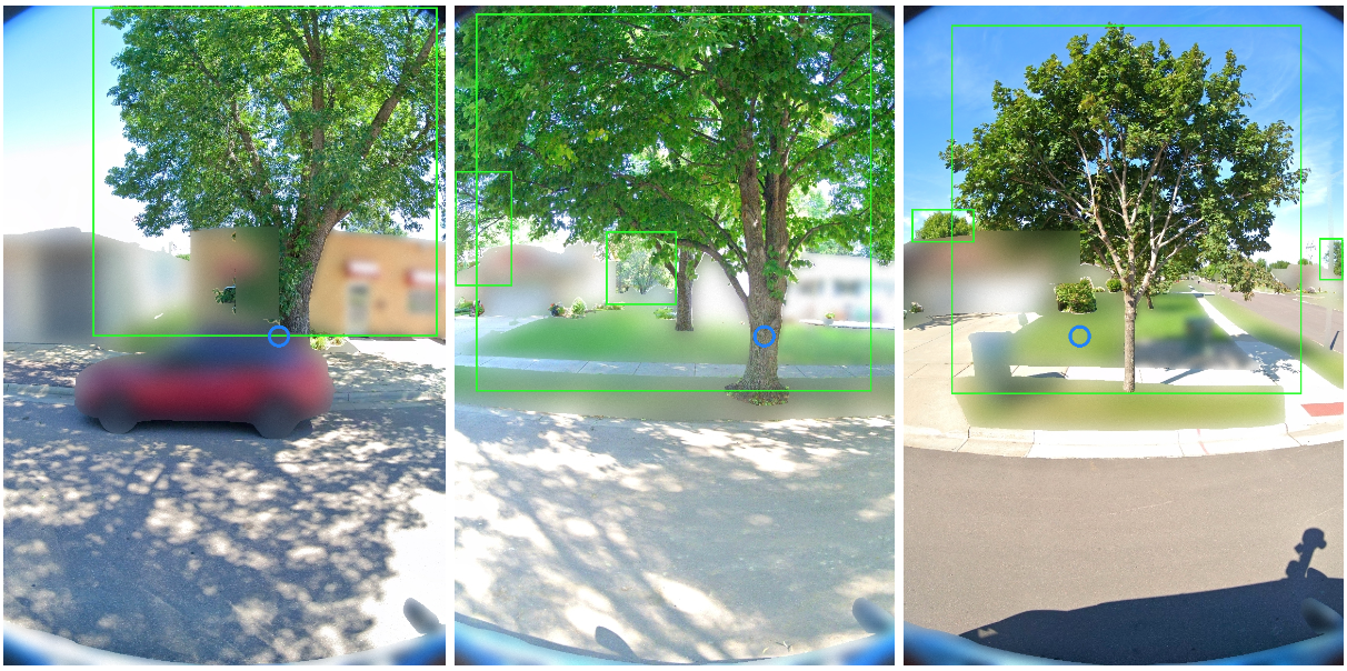
Selected Street View imagery from the Auto Arborist dataset. Green boxes represent tree detections (using a model trained on Open Images) and blue dots represent projected GPS location of the labeled tree.

One of the most important challenges for urban forest monitoring is to do well in cities that were not part of the training set. Vision models must contend with distribution shifts, where the training distribution differs from the test distribution from a new city. Genus distributions vary geographically (e.g., there are more Douglas fir in western Canada than in California) and can also vary based on city size (LA is much larger than Santa Monica and contains many more genera). Another challenge is the long-tailed, fine-grained nature of tree genera, which can be difficult to disambiguate even for human experts, with many genera being quite rare.

The long-tailed distribution across Auto Arborist categories. Most examples come from a few frequent categories, and many categories have far fewer examples. We characterize each genus as frequent, common, or rare based on the number of training examples. Note that the test data is split spatially from the training data within each city, so not all rare genera are seen in the test set.

Finally, there are a number of ways in which tree images can have noise. For one, there is temporal variation in deciduous trees (for example, when aerial imagery includes leaves, but street-level images are bare). Moreover, public arboreal censuses are not always up-to-date. Thus, sometimes trees have died (and are no longer visible) in the time since the tree census was taken. In addition, aerial data quality can be poor (missing or obscured, e.g., by clouds).

Our curation process sought to minimize these issues by (1) only keeping images with sufficient tree pixels, as determined by a semantic segmentation model, (2) only keeping reasonably recent images, and (3) only keeping images where the tree position was sufficiently close to the street level camera. We considered also optimizing for trees seen in spring and summer, but decided seasonal variation could be a useful cue — we thus also released the date of each image to enable the community to explore the effects of seasonal variability.

Benchmark and Evaluation
To evaluate the dataset, we designed a benchmark to measure domain generalization and performance in the long tail of the distribution. We generated training and test splits at three levels. First, we split within each city (based on latitude or longitude) to see how well a city generalizes to itself. Second, we aggregate city-level training sets into three regions, West, Central, and East, holding out one city from each region. Finally, we merge the training sets across the three regions. For each of these splits, we report both accuracy and class-averaged recall for frequent, common and rare species on the corresponding held-out test sets.

Using these metrics, we establish a performance baseline using standard modern convolutional models (ResNet). Our results demonstrate the benefits of a large-scale, geospatially distributed dataset such as Auto Arborist. First, we see that more training data helps — training on the entire dataset is better than training on a region, which is better than training on a single city.

The performance on each city’s test set when training on itself, on the region, and on the full training set.

Second, training on similar cities helps (and thus, having more coverage of cities helps). For example, if focusing on Seattle, then it is better to train on trees in Vancouver than Pittsburgh.

Cross-set performance, looking at the pairwise combination of train and test sets for each city. Note the block-diagonal structure, which highlights regional structure in the dataset.

Third, more data modalities and views help. The best performing models combine inputs from multiple Street View angles and overhead views. There remains much room for improvement, however, and this is where we believe the larger community of researchers can help.

Get Involved
By releasing the Auto Arborist Dataset, we step closer to the goal of affordable urban forest monitoring, enabling the computer vision community to tackle urban forest monitoring at scale for the first time. In the future, we hope to expand coverage to more North American cities (particularly in the South of the US and Mexico) and even worldwide. Further, we are excited to push the dataset to the more fine-grained species level and investigate more nuanced monitoring, including monitoring tree health and growth over time, and studying the effects of environmental factors on urban forests.

For more details, see our CVPR 2022 paper. This dataset is part of Google’s broader efforts to empower cities with data about urban forests, through the Environmental Insights Explorer Tree Canopy Lab and is available on our GitHub repo. If you represent a city that is interested in being included in the dataset please email auto-arborist+managers@googlegroups.com.

Acknowledgements
We would like to thank our co-authors Guanhang Wu, Trevor Edwards, Filip Pavetic, Bo Majewski, Shreyasee Mukherjee, Stanley Chan, John Morgan, Vivek Rathod, and Chris Bauer. We also thank Ruth Alcantara, Tanya Birch, and Dan Morris from Google AI for Nature and Society, John Quintero, Stafford Marquardt, Xiaoqi Yin, Puneet Lall, and Matt Manolides from Google Geo, Karan Gill, Tom Duerig, Abhijit Kundu, David Ross, Vighnesh Birodkar from Google Research (Perception team), and Pietro Perona for their support. This work was supported in part by the Resnick Sustainability Institute and was undertaken while Sara Beery was a Student Researcher at Google.

Read More

How AI creates photorealistic images from text

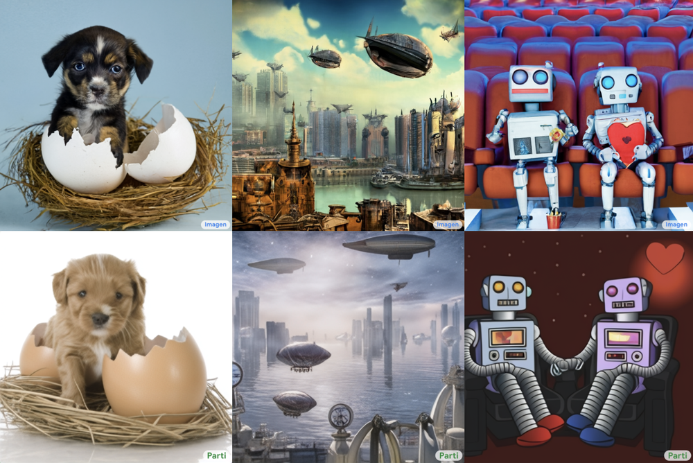
Pictures of puppy in a nest emerging from a cracked egg. Photos overlooking a steampunk city with airships. Picture of two robots having a romantic evening at the movies.

Have you ever seen a puppy in a nest emerging from a cracked egg? What about a photo that’s overlooking a steampunk city with airships? Or a picture of two robots having a romantic evening at the movies? These might sound far-fetched, but a novel type of machine learning technology called text-to-image generation makes them possible. These models can generate high-quality, photorealistic images from a simple text prompt.

Within Google Research, our scientists and engineers have been exploring text-to-image generation using a variety of AI techniques. After a lot of testing we recently announced two new text-to-image models — Imagen and Parti. Both have the ability to generate photorealistic images but use different approaches. We want to share a little more about how these models work and their potential.

How text-to-image models work

With text-to-image models, people provide a text description and the models produce images matching the description as closely as possible. This can be something as simple as “an apple” or “a cat sitting on a couch” to more complex details, interactions and descriptive indicators like “a cute sloth holding a small treasure chest. A bright golden glow is coming from the chest.”

A picture of a cute sloth holding a small treasure chest. A bright golden glow is coming from the chest

In the past few years, ML models have been trained on large image datasets with corresponding textual descriptions, resulting in higher quality images and a broader range of descriptions. This has sparked major breakthroughs in this area, including Open AI’s DALL-E 2.

How Imagen and Parti work

Imagen and Parti build on previous models. Transformer models are able to process words in relationship to one another in a sentence. They are foundational to how we represent text in our text-to-image models. Both models also use a new technique that helps generate images that more closely match the text description. While Imagen and Parti use similar technology, they pursue different, but complementary strategies.

Imagen is a Diffusion model, which learns to convert a pattern of random dots to images. These images first start as low resolution and then progressively increase in resolution. Recently, Diffusion models have seen success in both image and audio tasks like enhancing image resolution, recoloring black and white photos, editing regions of an image, uncropping images, and text-to-speech synthesis.

Parti’s approach first converts a collection of images into a sequence of code entries, similar to puzzle pieces. A given text prompt is then translated into these code entries and a new image is created. This approach takes advantage of existing research and infrastructure for large language models such as PaLM and is critical for handling long, complex text prompts and producing high-quality images.

These models have many limitations. For example, neither can reliably produce specific counts of objects (e.g. “ten apples”), nor place them correctly based on specific spatial descriptions (e.g. “a red sphere to the left of a blue block with a yellow triangle on it”). Also, as prompts become more complex, the models begin to falter, either missing details or introducing details that were not provided in the prompt. These behaviors are a result of several shortcomings, including lack of explicit training material, limited data representation, and lack of 3D awareness. We hope to address these gaps through broader representations and more effective integration into the text-to-image generation process.

Taking a responsible approach to Imagen and Parti

Text-to-image models are exciting tools for inspiration and creativity. They also come with risks related to disinformation, bias and safety. We’re having discussions around Responsible AI practices and the necessary steps to safely pursue this technology. As an initial step, we’re using easily identifiable watermarks to ensure people can always recognize an Imagen- or Parti-generated image. We’re also conducting experiments to better understand biases of the models, like how they represent people and cultures, while exploring possible mitigations. The Imagen and Parti papers provide extensive discussion of these issues.

What’s next for text-to-image models at Google

We will push on new ideas that combine the best of both models, and expand to related tasks such as adding the ability to interactively generate and edit images through text. We’re also continuing to conduct in-depth comparisons and evaluations to align with our Responsible AI Principles. Our goal is to bring user experiences based on these models to the world in a safe, responsible way that will inspire creativity.

Read More

Meet the Omnivore: Director of Photography Revs Up NVIDIA Omniverse to Create Sleek Car Demo

Editor’s note: This post is a part of our Meet the Omnivore series, which features individual creators and developers who use NVIDIA Omniverse to accelerate their 3D workflows and create virtual worlds.

A camera begins in the sky, flies through some trees and smoothly exits the forest, all while precisely tracking a car driving down a dirt path. This would be all but impossible in the real world, according to film and photography director Brett Danton.

But Danton made what he calls this “impossible camera move” possible for an automotive commercial — at home, with cinematic quality and physical accuracy.

He pulled off the feat using NVIDIA Omniverse, a 3D design collaboration and world simulation platform that enhanced his typical creative workflow and connected various apps he uses, including Autodesk Maya, Epic Games Unreal Engine and Omniverse Create.

With 30+ years of experience in the digital imagery industry, U.K.-based Danton creates advertisements for international clients, showcasing products ranging from cosmetics to cars.

His latest projects, like the above using a Volvo car, demonstrate how a physical location can be recreated for a virtual shoot, delivering photorealistic rendered sequences that match cinematic real-world footage.

“This breaks from traditional imagery and shifts the gears of what’s possible in the digital arts, allowing multiple deliverables inside the one asset,” Danton said.

The physically accurate simulation capabilities of Omniverse took Danton’s project the extra mile, animating a photorealistic car that reacts to the dirt road’s uneven surface as it would in real life.

And by working with Universal Scene Description (USD)-based assets from connected digital content creation tools like Autodesk Maya and Unreal Engine in Omniverse, Danton collaborated with other art departments from his home, just outside of London.

“Omniverse gives me an entire studio on my desktop,” Danton said. “It’s impossible to tell the difference between the real location and what’s been created in Omniverse, and I know that because I went and stood in the real location to create the virtual set.”

Real-Time Collaboration for Multi-App Workflows

To create the forest featured in the car commercial, Danton collaborated with award-winning design studio Ars Thanea. The team shot countless 100-megapixel images to use as references, resulting in a point cloud — or set of data points representing 3D shapes in space — that totaled 250 gigabytes.

The team then used Omniverse as the central hub for all of the data exchange, accelerated by NVIDIA RTX GPUs. Autodesk Maya served as the entry point for camera animation and initial lighting before the project’s data was brought into Omniverse with an Omniverse Connector.

And with the Omniverse Create app, the artists placed trees by hand, created tree patches and tweaked them to fit the forest floor. Omniverse-based real-time collaboration was key for enabling high-profile visual effects artists to work together remotely and on site, Danton said.

Omniverse Create uses Pixar’s USD format to accelerate advanced scene composition and assemble, light, simulate and render 3D scenes in real time.

Photorealistic Lighting With Path Tracing

When directing projects in physical production sites and studios, Danton said he was limited in what he could achieve with lighting — depending on resources, time of day and many other factors. Omniverse removes such creative limitations.

“I can now pre-visualize any of the shots I want to take, and on top of that, I can light them in Omniverse in a photorealistic way,” Danton said.

When he moves a light in Omniverse, the scene reacts exactly the way it would in the real world.

This ability, enabled by Omniverse’s RTX-powered real-time ray tracing and path tracing, is Danton’s favorite aspect of the platform. It lets him create photorealistic, cinematic sequences with “true feel of light,” which wasn’t possible before, he said.

In the Volvo car clip above, for example, the Omniverse lighting reacts on the car as it would in the forest, with physically accurate reflections and light bouncing off the windows.

“I’ve tried other software before, and Omniverse is far superior to anything else I have seen because of its real-time rendering and collaborative workflow capabilities,” Danton said.

Join in on the Creation

Creators across the world can experience NVIDIA Omniverse for free, and enterprise teams can use the platform for their projects.

Plus, join the #MadeInMachinima contest, running through June 27, for a chance to win the latest NVIDIA Studio laptop.

Learn more about Omniverse by watching GTC sessions on demand — featuring visionaries from the Omniverse team, Adobe, Autodesk, Epic Games, Pixar, Unity and Walt Disney Studios.

Follow Omniverse on Instagram, Twitter, YouTube and Medium for additional resources and inspiration. Check out the Omniverse forums and join our Discord Server to chat with the community.

The post Meet the Omnivore: Director of Photography Revs Up NVIDIA Omniverse to Create Sleek Car Demo appeared first on NVIDIA Blog.

Read More

Artem Cherkasov and Olexandr Isayev on Democratizing Drug Discovery With NVIDIA GPUs

It may seem intuitive that AI and deep learning can speed up workflows — including novel drug discovery, a typically years-long and several-billion-dollar endeavor.

But professors Artem Cherkasov and Olexandr Isayev were surprised to find that no recent academic papers provided a comprehensive, global research review of how deep learning and GPU-accelerated computing impact drug discovery.

In March, they published a paper in Nature to fill this gap, presenting an up-to-date review of the state of the art for GPU-accelerated drug discovery techniques.

Cherkasov, a professor in the department of urologic sciences at the University of British Columbia, and Isayev, an assistant professor of chemistry at Carnegie Mellon University, join NVIDIA AI Podcast host Noah Kravitz this week to discuss how GPUs can help democratize drug discovery.

In addition, the guests cover their inspiration and process for writing the paper, talk about NVIDIA technologies that are transforming the role of AI in drug discovery, and give tips for adopting new approaches to research.

You Might Also Like

Lending a Helping Hand: Jules Anh Tuan Nguyen on Building a Neuroprosthetic

Is it possible to manipulate things with your mind? Possibly. University of Minnesota postdoctoral researcher Jules Anh Tuan Nguyen discusses allowing amputees to control their prosthetic limbs with their thoughts, using neural decoders and deep learning.

AI of the Tiger: Conservation Biologist Jeremy Dertien on Real-Time Poaching Prevention

Fewer than 4,000 tigers remain in the wild due to a combination of poaching, habitat loss and environmental pressures. Clemson University’s Jeremy Dertien discusses using AI-equipped cameras to monitor poaching to protect a majority of the world’s remaining tiger populations.

Wild Things: 3D Reconstructions of Endangered Species with NVIDIA’s Sifei Liu

Studying endangered species can be difficult, as they’re elusive, and the act of observing them can disrupt their lives. Sifei Liu, a senior research scientist at NVIDIA, discusses how scientists can avoid these pitfalls by studying AI-generated 3D representations of these endangered species.

Subscribe to the AI Podcast: Now Available on Amazon Music

You can now listen to the AI Podcast through Amazon Music.

Also get the AI Podcast through iTunes, Google Podcasts, Google Play, Castbox, DoggCatcher, Overcast, PlayerFM, Pocket Casts, Podbay, PodBean, PodCruncher, PodKicker, Soundcloud, Spotify, Stitcher and TuneIn.

Make the AI Podcast better: Have a few minutes to spare? Fill out our listener survey.


The post Artem Cherkasov and Olexandr Isayev on Democratizing Drug Discovery With NVIDIA GPUs appeared first on NVIDIA Blog.

Read More

Accelerate your career with ML skills through the AWS Machine Learning Engineer Scholarship

Amazon Web Services and Udacity are partnering to offer free services to educate developers of all skill levels on machine learning (ML) concepts with the AWS Machine Learning Engineer Scholarship program. The program offers free enrollment to the AWS Machine Learning Foundations course and 325 scholarships awarded to the AWS Machine Learning Engineer Nanodegree, a $2,000 USD value, powered through Udacity.

Machine learning will not only change the way we work and live, but also open pathways to millions of new jobs, with the World Economic Forum estimating 97 million new roles may be created by 2025 in AI and ML. Gaining access to the job-ready skills to break into an ML career encounters high cost to traditional education and rigorous content, with a lack of real-world application from theory into practice. AWS is invested in addressing these challenges by providing free educational content and hands-on learning, such as exploring reinforcement learning concepts with AWS DeepRacer, as well as a community of learner support with technical experts and like-minded peers.

The AWS Machine Learning Engineer Nanodegree Program gave me a solid footing in understanding the foundational building blocks of Machine Learning workflows,” said Jikmyan Mangut Sunday, AWS Machine Learning Scholarship Alumni. “This shaped my knowledge of the fundamental concepts in building state-of-the-art Machine Learning models. Udacity curated learning materials that were easy to grasp and applicable to every field of endeavor, my learning experience was challenging and fun-filled.

AWS is also collaborating with Girls in Tech and National Society for Black Engineers, to provide scholarships to women and underrepresented groups in tech. Organizations like these aims to inspire, support, train, and empower people from underrepresented groups to pursue careers in tech. In partnership, AWS will aid in providing access and resources to programs such as the AWS Machine Learning Engineer Scholarship Program to increase the diversity and talent in technical roles.

Tech needs representation from women, BIPOC, and other marginalized communities in every aspect of our industry,” says Adriana Gascoigne, founder and CEO of Girls in Tech. “Girls in Tech applauds our collaborator AWS, as well as Udacity, for breaking down the barriers that so often leave women behind in tech. Together, we aim to give everyone a seat at the table.

Open pathways to new career opportunities

Learners in the program are able to apply theory into hands on application to a suite of AWS ML services including AWS DeepRacer, Amazon SageMaker, and AWS DeepComposer. As many struggle to get started with machine learning, the scholarship program provides easy to learn, self-paced modules to provide the flexibility at a self-guided pace. Throughout the course journey, learners will have access to a supportive online community for technical assistance through Udacity tutors.

Before taking the program, the many tools provided by AWS seemed frustrating but now I have a good grasp of them. I learned how to organize my code and work in a professional setting,” said Kariem Gazer AWS Machine Learning Scholarship Alumni. “The organized modules, follow up quizzes, and personalized feedback all made the learning experience smoother and concrete.

Gain ML skills beyond the classroom

The AWS Machine Learning Engineer Scholarship program is open to all developers interested in expanding their ML skills and expertise through AWS curated content and services. Applicants 18 years of age or older are invited to register for the program. All applicants will have immediate classroom access to the free AWS ML Foundations course upon application completion.

Phase 1: AWS Machine Learning Foundations Course

  • Learn object-oriented programming skills, including writing clean and modularized code and understanding the fundamental aspects of ML.
  • Learn reinforcement learning with AWS DeepRacer and generative AI with AWS DeepComposer.
  • Take advantage of support through the Discourse Tech community with technical moderators.
  • Receive a certificate for course completion and take an online assessment quiz to receive a full scholarship to the AWS Machine Learning Engineer Nanodegree program.
  • Dedicate 3–5 hours a week on the course and work towards earning one of the follow-up Nanodegree program scholarships.

Phase 2: Full scholarship to the AWS Machine Learning Engineer Udacity Nanodegree ($2,000 USD value)

  • Learn advanced ML techniques and algorithms, including how to package and deploy your models to a production environment.
  • Acquire practical experience such as using Amazon SageMaker to prepare you for a career in ML.
  • Take advantage of community support through a learner connect program for technical assistance and learner engagement.
  • Dedicate 5–10 hours a week on the course to earn an Udacity Nanodegree certificate.

Program dates

June 21, 2022 Scholarship applications open and students are automatically enrolled in the AWS Machine Learning Foundations Course (Phase 1)

July 21, 2022 Scholarship applications close
November 23, 2022 AWS Machine Learning Foundations Course (Phase 1) ends
December 6, 2022 AWS Machine Learning Engineer Scholarship winners announced
December 8, 2022 AWS Machine Learning Engineer Nanodegree (Phase 2) opens
March 22, 2023 AWS Machine Learning Engineer Nanodegree (Phase 2) closes

Connect with the ML community and take the next step

Connect with experts and like-minded aspiring ML developers on the AWS Machine Learning Discord and enroll today in the AWS Machine Learning Engineer Scholarship program.


About the Author

Anastacia Padilla is a Product Marketing Manager for AWS AI & ML Education. She spends her time building and evangelizing offerings for the aspiring ML developer community to upskill students and underrepresented groups in tech. She is focused on democratizing AI & ML education to be accessible to all who want to learn.

Read More

Identify mangrove forests using satellite image features using Amazon SageMaker Studio and Amazon SageMaker Autopilot – Part 2

Mangrove forests are an import part of a healthy ecosystem, and human activities are one of the major reasons for their gradual disappearance from coastlines around the world. Using a machine learning (ML) model to identify mangrove regions from a satellite image gives researchers an effective way to monitor the size of the forests over time. In Part 1 of this series, we showed how to gather satellite data in an automated fashion and analyze it in Amazon SageMaker Studio with interactive visualization. In this post, we show how to use Amazon SageMaker Autopilot to automate the process of building a custom mangrove classifier.

Train a model with Autopilot

Autopilot provides a balanced way of building several models and selecting the best one. While creating multiple combinations of different data preprocessing techniques and ML models with minimal effort, Autopilot provides complete control over these component steps to the data scientist, if desired.

You can use Autopilot using one of the AWS SDKs (details available in the API reference guide for Autopilot) or through Studio. We use Autopilot in our Studio solution following the steps outlined in this section:

  1. On the Studio Launcher page, choose the plus sign for New Autopilot experiment.
  2. For Connect your data, select Find S3 bucket, and enter the bucket name where you kept the training and test datasets.
  3. For Dataset file name, enter the name of the training data file you created in the Prepare the training data section in Part 1.
  4. For Output data location (S3 bucket), enter the same bucket name you used in step 2.
  5. For Dataset directory name, enter a folder name under the bucket where you want Autopilot to store artifacts.
  6. For Is your S3 input a manifest file?, choose Off.
  7. For Target, choose label.
  8. For Auto deploy, choose Off.
  9. Under the Advanced settings, for Machine learning problem type, choose Binary Classification.
  10. For Objective metric, choose AUC.
  11. For Choose how to run your experiment, choose No, run a pilot to create a notebook with candidate definitions.
  12. Choose Create Experiment.

    For more information about creating an experiment, refer to Create an Amazon SageMaker Autopilot experiment.It may take about 15 minutes to run this step.
  13. When complete, choose Open candidate generation notebook, which opens a new notebook in read-only mode.
  14. Choose Import notebook to make the notebook editable.
  15. For Image, choose Data Science.
  16. For Kernel, choose Python 3.
  17. Choose Select.

This auto-generated notebook has detailed explanations and provides complete control over the actual model building task to follow. A customized version of the notebook, where a classifier is trained using Landsat satellite bands from 2013, is available in the code repository under notebooks/mangrove-2013.ipynb.

The model building framework consists of two parts: feature transformation as part of the data processing step, and hyperparameter optimization (HPO) as part of the model selection step. All the necessary artifacts for these tasks were created during the Autopilot experiment and saved in Amazon Simple Storage Service (Amazon S3). The first notebook cell downloads those artifacts from Amazon S3 to the local Amazon SageMaker file system for inspection and any necessary modification. There are two folders: generated_module and sagemaker_automl, where all the Python modules and scripts necessary to run the notebook are stored. The various feature transformation steps like imputation, scaling, and PCA are saved as generated_modules/candidate_data_processors/dpp*.py.

Autopilot creates three different models based on the XGBoost, linear learner, and multi-layer perceptron (MLP) algorithms. A candidate pipeline consists of one of the feature transformations options, known as data_transformer, and an algorithm. A pipeline is a Python dictionary and can be defined as follows:

candidate1 = {
    "data_transformer": {
        "name": "dpp5",
        "training_resource_config": {
            "instance_type": "ml.m5.4xlarge",
            "instance_count": 1,
            "volume_size_in_gb":  50
        },
        "transform_resource_config": {
            "instance_type": "ml.m5.4xlarge",
            "instance_count": 1,
        },
        "transforms_label": True,
        "transformed_data_format": "application/x-recordio-protobuf",
        "sparse_encoding": True
    },
    "algorithm": {
        "name": "xgboost",
        "training_resource_config": {
            "instance_type": "ml.m5.4xlarge",
            "instance_count": 1,
        },
    }
}

In this example, the pipeline transforms the training data according to the script in generated_modules/candidate_data_processors/dpp5.py and builds an XGBoost model. This is where Autopilot provides complete control to the data scientist, who can pick the automatically generated feature transformation and model selection steps or build their own combination.

You can now add the pipeline to a pool for Autopilot to run the experiment as follows:

from sagemaker_automl import AutoMLInteractiveRunner, AutoMLLocalCandidate

automl_interactive_runner = AutoMLInteractiveRunner(AUTOML_LOCAL_RUN_CONFIG)
automl_interactive_runner.select_candidate(candidate1)

This is an important step where you can decide to keep only a subset of candidates suggested by Autopilot, based on subject matter expertise, to reduce the total runtime. For now, keep all Autopilot suggestions, which you can list as follows:

automl_interactive_runner.display_candidates()
Candidate Name Algorithm Feature Transformer
dpp0-xgboost xgboost dpp0.py
dpp1-xgboost xgboost dpp1.py
dpp2-linear-learner linear-learner dpp2.py
dpp3-xgboost xgboost dpp3.py
dpp4-xgboost xgboost dpp4.py
dpp5-xgboost xgboost dpp5.py
dpp6-mlp mlp dpp6.py

The full Autopilot experiment is done in two parts. First, you need to run the data transformation jobs:

automl_interactive_runner.fit_data_transformers(parallel_jobs=7)

This step should complete in about 30 minutes for all the candidates, if you make no further modifications to the dpp*.py files.

The next step is to build the best set of models by tuning the hyperparameters for the respective algorithms. The hyperparameters are usually divided into two parts: static and tunable. The static hyperparameters remain unchanged throughout the experiment for all candidates that share the same algorithm. These hyperparameters are passed to the experiment as a dictionary. If you choose to pick the best XGBoost model by maximizing AUC from three rounds of a five-fold cross-validation scheme, the dictionary looks like the following code:

{
    'objective': 'binary:logistic',
    'eval_metric': 'auc',
    '_kfold': 5,
    '_num_cv_round': 3,
} 

For the tunable hyperparameters, you need to pass another dictionary with ranges and scaling type:

{
    'num_round': IntegerParameter(64, 1024, scaling_type='Logarithmic'),
    'max_depth': IntegerParameter(2, 8, scaling_type='Logarithmic'),
        'eta': ContinuousParameter(1e-3, 1.0, scaling_type='Logarithmic'),
...    
}

The complete set of hyperparameters is available in the mangrove-2013.ipynb notebook.

To create an experiment where all seven candidates can be tested in parallel, create a multi-algorithm HPO tuner:

multi_algo_tuning_parameters = automl_interactive_runner.prepare_multi_algo_parameters(
    objective_metrics=ALGORITHM_OBJECTIVE_METRICS,
    static_hyperparameters=STATIC_HYPERPARAMETERS,
    hyperparameters_search_ranges=ALGORITHM_TUNABLE_HYPERPARAMETER_RANGES)

The objective metrics are defined independently for each algorithm:

ALGORITHM_OBJECTIVE_METRICS = {
    'xgboost': 'validation:auc',
    'linear-learner': 'validation:roc_auc_score',
    'mlp': 'validation:roc_auc',
}

Trying all possible values of hyperparameters for all the experiments is wasteful; you can adopt a Bayesian strategy to create an HPO tuner:

multi_algo_tuning_inputs = automl_interactive_runner.prepare_multi_algo_inputs()
ase_tuning_job_name = "{}-tuning".format(AUTOML_LOCAL_RUN_CONFIG.local_automl_job_name)

tuner = HyperparameterTuner.create(
    base_tuning_job_name=base_tuning_job_name,
    strategy='Bayesian',
    objective_type='Maximize',
    max_parallel_jobs=10,
    max_jobs=50,
    **multi_algo_tuning_parameters,
)

In the default setting, Autopilot picks 250 jobs in the tuner to pick the best model. For this use case, it’s sufficient to set max_jobs=50 to save time and resources, without any significant penalty in terms of picking the best set of hyperparameters. Finally, submit the HPO job as follows:

tuner.fit(inputs=multi_algo_tuning_inputs, include_cls_metadata=None)

The process takes about 80 minutes on ml.m5.4xlarge instances. You can monitor progress on the SageMaker console by choosing Hyperparameter tuning jobs under Training in the navigation pane.

You can visualize a host of useful information, including the performance of each candidate, by choosing the name of the job in progress.

Finally, compare the model performance of the best candidates as follows:

from sagemaker.analytics import HyperparameterTuningJobAnalytics

SAGEMAKER_SESSION = AUTOML_LOCAL_RUN_CONFIG.sagemaker_session
SAGEMAKER_ROLE = AUTOML_LOCAL_RUN_CONFIG.role

tuner_analytics = HyperparameterTuningJobAnalytics(
    tuner.latest_tuning_job.name, sagemaker_session=SAGEMAKER_SESSION)

df_tuning_job_analytics = tuner_analytics.dataframe()

df_tuning_job_analytics.sort_values(
    by=['FinalObjectiveValue'],
    inplace=True,
    ascending=False if tuner.objective_type == "Maximize" else True)

# select the columns to display and rename
select_columns = ["TrainingJobDefinitionName", "FinalObjectiveValue", "TrainingElapsedTimeSeconds"]
rename_columns = {
	"TrainingJobDefinitionName": "candidate",
	"FinalObjectiveValue": "AUC",
	"TrainingElapsedTimeSeconds": "run_time"  
}

# Show top 5 model performances
df_tuning_job_analytics.rename(columns=rename_columns)[rename_columns.values()].set_index("candidate").head(5)
candidate AUC run_time (s)
dpp6-mlp 0.96008 2711.0
dpp4-xgboost 0.95236 385.0
dpp3-xgboost 0.95095 202.0
dpp4-xgboost 0.95069 458.0
dpp3-xgboost 0.95015 361.0

The top performing model based on MLP, while marginally better than the XGBoost models with various choices of data processing steps, also takes a lot longer to train. You can find important details about the MLP model training, including the combination of hyperparameters used, as follows:

df_tuning_job_analytics.loc[df_tuning_job_analytics.TrainingJobName==best_training_job].T.dropna() 
TrainingJobName mangrove-2-notebook–211021-2016-012-500271c8
TrainingJobStatus Completed
FinalObjectiveValue 0.96008
TrainingStartTime 2021-10-21 20:22:55+00:00
TrainingEndTime 2021-10-21 21:08:06+00:00
TrainingElapsedTimeSeconds 2711
TrainingJobDefinitionName dpp6-mlp
dropout_prob 0.415778
embedding_size_factor 0.849226
layers 256
learning_rate 0.00013862
mini_batch_size 317
network_type feedforward
weight_decay 1.29323e-12

Create an inference pipeline

To generate inference on new data, you have to construct an inference pipeline on SageMaker to host the best model that can be called later to generate inference. The SageMaker pipeline model requires three containers as its components: data transformation, algorithm, and inverse label transformation (if numerical predictions need to be mapped on to non-numerical labels). For brevity, only part of the required code is shown in the following snippet; the complete code is available in the mangrove-2013.ipynb notebook:

from sagemaker.estimator import Estimator
from sagemaker import PipelineModel
from sagemaker_automl import select_inference_output

…
# Final pipeline model 
model_containers = [best_data_transformer_model, best_algo_model]
if best_candidate.transforms_label:
	model_containers.append(best_candidate.get_data_transformer_model(
    	transform_mode="inverse-label-transform",
    	role=SAGEMAKER_ROLE,
    	sagemaker_session=SAGEMAKER_SESSION))

# select the output type
model_containers = select_inference_output("BinaryClassification", model_containers, output_keys=['predicted_label'])

After the model containers are built, you can construct and deploy the pipeline as follows:

from sagemaker import PipelineModel

pipeline_model = PipelineModel(
	name=f"mangrove-automl-2013",
	role=SAGEMAKER_ROLE,
	models=model_containers,
	vpc_config=AUTOML_LOCAL_RUN_CONFIG.vpc_config)

pipeline_model.deploy(initial_instance_count=1,
                  	instance_type='ml.m5.2xlarge',
                  	endpoint_name=pipeline_model.name,
                  	wait=True)

The endpoint deployment takes about 10 minutes to complete.

Get inference on the test dataset using an endpoint

After the endpoint is deployed, you can invoke it with a payload of features B1–B7 to classify each pixel in an image as either mangrove (1) or other (0):

import boto3
sm_runtime = boto3.client('runtime.sagemaker')

pred_labels = []
with open(local_download, 'r') as f:
    for i, row in enumerate(f):
        payload = row.rstrip('n')
        x = sm_runtime.invoke_endpoint(EndpointName=inf_endpt,
                                   	ContentType="text/csv",
                                   	Body=payload)
        pred_labels.append(int(x['Body'].read().decode().strip()))

Complete details on postprocessing the model predictions for evaluation and plotting are available in notebooks/model_performance.ipynb.

Get inference on the test dataset using a batch transform

Now that you have created the best-performing model with Autopilot, we can use the model for inference. To get inference on large datasets, it’s more efficient to use a batch transform. Let’s generate predictions on the entire dataset (training and test) and append the results to the features, so that we can perform further analysis to, for instance, check the predicted vs. actuals and the distribution of features amongst predicted classes.

First, we create a manifest file in Amazon S3 that points to the locations of the training and test data from the previous data processing steps:

import boto3
data_bucket = <Name of the S3 bucket that has the training data>
prefix = "LANDSAT_LC08_C01_T1_SR/Year2013"
manifest = "[{{"prefix": "s3://{}/{}/"}},n"train.csv",n"test.csv"n]".format(data_bucket, prefix)
s3_client = boto3.client('s3')
s3_client.put_object(Body=manifest, Bucket=data_bucket, Key=f"{prefix}/data.manifest")

Now we can create a batch transform job. Because our input train and test dataset have label as the last column, we need to drop it during inference. To do that, we pass InputFilter in the DataProcessing argument. The code "$[:-2]" indicates to drop the last column. The predicted output is then joined with the source data for further analysis.

In the following code, we construct the arguments for the batch transform job and then pass to the create_transform_job function:

from time import gmtime, strftime

batch_job_name = "Batch-Transform-" + strftime("%Y-%m-%d-%H-%M-%S", gmtime())
output_location = "s3://{}/{}/batch_output/{}".format(data_bucket, prefix, batch_job_name)
input_location = "s3://{}/{}/data.manifest".format(data_bucket, prefix)

request = {
    "TransformJobName": batch_job_name,
    "ModelName": pipeline_model.name,
    "TransformOutput": {
        "S3OutputPath": output_location,
        "Accept": "text/csv",
        "AssembleWith": "Line",
    },
    "TransformInput": {
        "DataSource": {"S3DataSource": {"S3DataType": "ManifestFile", "S3Uri": input_location}},
        "ContentType": "text/csv",
        "SplitType": "Line",
        "CompressionType": "None",
    },
    "TransformResources": {"InstanceType": "ml.m4.xlarge", "InstanceCount": 1},
    "DataProcessing": {"InputFilter": "$[:-2]", "JoinSource": "Input"}
}

sagemaker = boto3.client("sagemaker")
sagemaker.create_transform_job(**request)
print("Created Transform job with name: ", batch_job_name)

You can monitor the status of the job on the SageMaker console.

Visualize model performance

You can now visualize the performance of the best model on the test dataset, consisting of regions from India, Myanmar, Cuba, and Vietnam, as a confusion matrix. The model has a high recall value for pixels representing mangroves, but only about 75% precision. The precision of non-mangrove or other pixels stand at 99% with an 85% recall. You can tune the probability cutoff of the model predictions to adjust the respective values depending on the particular use case.

It’s worth noting that the results are a significant improvement over the built-in smileCart model.

Visualize model predictions

Finally, it’s useful to observe the model performance on specific regions on the map. In the following image, the mangrove area in the India-Bangladesh border is depicted in red. Points sampled from the Landsat image patch belonging to the test dataset are superimposed on the region, where each point is a pixel that the model determines to be representing mangroves. The blue points are classified correctly by the model, whereas the black points represent mistakes by the model.

The following image shows only the points that the model predicted to not represent mangroves, with the same color scheme as the preceding example. The gray outline is the part of the Landsat patch that doesn’t include any mangroves. As is evident from the image, the model doesn’t make any mistake classifying points on water, but faces a challenge when distinguishing pixels representing mangroves from those representing regular foliage.

The following image shows model performance on the Myanmar mangrove region.

In the following image, the model does a better job identifying mangrove pixels.

Clean up

The SageMaker inference endpoint continues to incur cost if left running. Delete the endpoint as follows when you’re done:

sagemaker.delete_endpoint(EndpointName=pipeline_model.name)

Conclusion

This series of posts provided an end-to-end framework for data scientists for solving GIS problems. Part 1 showed the ETL process and a convenient way to visually interact with the data. Part 2 showed how to use Autopilot to automate building a custom mangrove classifier.

You can use this framework to explore new satellite datasets containing a richer set of bands useful for mangrove classification and explore feature engineering by incorporating domain knowledge.


About the Authors

Andrei Ivanovic is an incoming Master’s of Computer Science student at the University of Toronto and a recent graduate of the Engineering Science program at the University of Toronto, majoring in Machine Intelligence with a Robotics/Mechatronics minor. He is interested in computer vision, deep learning, and robotics. He did the work presented in this post during his summer internship at Amazon.

David Dong is a Data Scientist at Amazon Web Services.

Arkajyoti Misra is a Data Scientist at Amazon LastMile Transportation. He is passionate about applying Computer Vision techniques to solve problems that helps the earth. He loves to work with non-profit organizations and is a founding member of ekipi.org.

Read More

Identify mangrove forests using satellite image features using Amazon SageMaker Studio and Amazon SageMaker Autopilot – Part 1

The increasing ubiquity of satellite data over the last two decades is helping scientists observe and monitor the health of our constantly changing planet. By tracking specific regions of the Earth’s surface, scientists can observe how regions like forests, water bodies, or glaciers change over time. One such region of interest for geologists is mangrove forests. These forests are essential to the overall health of the planet and are one of the many areas across the world that are impacted by human activities. In this post, we show how to get access to satellite imagery data containing mangrove forests and how to visually interact with the data in Amazon SageMaker Studio. In Part 2 of this series, we show how to train a machine learning (ML) model using Amazon SageMaker Autopilot to identify those forests from a satellite image.

Overview of solution

A large number of satellites orbit the Earth, scanning its surface on a regular basis. Typical examples of such satellites are Landsat, Sentinel, CBERS, and MODIS, to name a few. You can access both recent and historical data captured by these satellites at no cost from multiple providers like USGS EarthExplorer, Land Viewer, or Copernicus Open Access Hub. Although they provide an excellent service to the scientific community by making their data freely available, it takes a significant amount of effort to gain familiarity with the interfaces of the respective providers. Additionally, such data from satellites is made available in different formats and may not comply with the standard Geographical Information Systems (GIS) data formatting. All of these challenges make it extremely difficult for newcomers to GIS to prepare a suitable dataset for ML model training.

Platforms like Google Earth Engine (GEE) and Earth on AWS make a wide variety of satellite imagery data available in a single portal that eases searching for the right dataset and standardizes the ETL (extract, transform, and load) component of the ML workflow in a convenient, beginner-friendly manner. GEE additionally provides a coding platform where you can programmatically explore the dataset and build a model in JavaScript. The Python API for GEE lacks the maturity of its JavaScript counterpart; however, that gap is sufficiently bridged by the open-sourced project geemap.

In this series of posts, we present a complete end-to-end example of building an ML model in the GIS space to detect mangrove forests from satellite images. Our goal is to provide a template solution that ML engineers and data scientists can use to explore and interact with the satellite imagery, make the data available in the right format for building a classifier, and have the option to validate model predictions visually. Specifically, we walk through the following:

  • How to download satellite imagery data to a Studio environment
  • How to interact with satellite data and perform exploratory data analysis in a Studio notebook
  • How to automate training an ML model in Autopilot

Build the environment

The solution presented in this post is built in a Studio environment. To configure the environment, complete the following steps:

  1. Add a new SageMaker domain user and launch the Studio app. (For instructions, refer to Get Started.)
  2. Open a new Studio notebook by choosing the plus sign under Notebook and compute resources (make sure to choose the Data Science SageMaker image).
  3. Clone the mangrove-landcover-classification Git repository, which contains all the code used for this post. (For instructions, refer to Clone a Git Repository in SageMaker Studio).
  4. Open the notebook notebooks/explore_mangrove_data.ipynb.
  5. Run the first notebook cell to pip install all the required dependencies listed in the requirements.txt file in the root folder.
  6. Open a new Launcher tab and open a system terminal found in the Utilities and files section.
  7. Install the Earth Engine API:
    pip install earthengine-api

  8. Authenticate Earth Engine:
    earthengine authenticate

  9. Follow the Earth Engine link in the output and sign up as a developer so that you can access GIS data from a notebook.

Mangrove dataset

The Global Mangrove Forest Distribution (GMFD) is one of the most cited datasets used by researchers in the area. The dataset, which contains labeled mangrove regions at a 30-meter resolution from around the world, is curated from more than 1,000 Landsat images obtained from the USGS EROS Center. One of the disadvantages of using the dataset is that it was compiled in 2000. In the absence of a newer dataset that is as comprehensive as the GMFD, we decided to use it because it serves the purpose of demonstrating an ML workload in the GIS space.

Given the visual nature of GIS data, it’s critical for ML practitioners to be able to interact with satellite images in an interactive manner with full map functionalities. Although GEE provides this functionality through a browser interface, it’s only available in JavaScript. Fortunately, the open-sourced project geemap aids data scientists by providing those functionalities in Python.

Go back to the explore_mangrove_data.ipynb notebook you opened earlier and follow the remaining cells to understand how to use simple interactive maps in the notebook.

  1. Start by importing Earth Engine and initializing it:
    import ee
    import geemap.eefolium as geemap
    ee.Initialize()

  2. Now import the satellite image collection from the database:
    mangrove_images_landsat = ee.ImageCollection('LANDSAT/MANGROVE_FORESTS')

  3. Extract the collection, which contains just one set:
    mangrove_images_landsat = mangrove_images_landsat.first()

  4. To visualize the data on a map, you first need to instantiate a map through geemap:
    mangrove_map = geemap.Map()

  5. Next, define some parameters that make it easy to visualize the data on a world map:
    mangrovesVis = {
          min: 0,
          max: 1.0,
          'palette': ['d40115'],
        }

  6. Now add the data as a layer on the map instantiated earlier with the visualization parameters:
    mangrove_map.addLayer(mangrove_images_landsat, mangrovesVis, 'Mangroves')

You can add as many layers as you want to the map and then interactively turn them on or off for a cleaner view when necessary. Because mangrove forests aren’t everywhere on the earth, it makes sense to center the map to a coastal region with known mangrove forests and then render the map on the notebook as follows:

mangrove_map.setCenter(-81, 25, 9)
mangrove_map

The latitude and longitude chosen here, 25 degrees north and 81 degrees west, respectively, correspond to the gulf coast of Florida, US. The map is rendered at a zoom level of 9, where a higher number provides a more closeup view.

You can obtain some useful information about the dataset by accessing the associated metadata as follows:

geemap.image_props(mangrove_images_landsat).getInfo()

You get the following output:

{'IMAGE_DATE': '2000-01-01',
 'NOMINAL_SCALE': 30.359861978395436,
 'system:asset_size': '41.133541 MB',
 'system:band_names': ['1'],
 'system:id': 'LANDSAT/MANGROVE_FORESTS/2000',
 'system:index': '2000',
 'system:time_end': '2001-01-01 00:00:00',
 'system:time_start': '2000-01-01 00:00:00',
 'system:version': 1506796895089836
}

Most of the fields in the metadata are self-explanatory, except for the band names. The next section discusses this field in more detail.

Landsat dataset

The following image is a satellite image of an area at the border of French Guiana and Suriname, where mangrove forests are common. The left image shows a raw satellite image of the region; the image on the right depicts the GMFD data superimposed on it. Pixels representing mangroves are shown in red. It’s quite evident from the side-by-side comparison that there is no straightforward visual cue in either structure or color in the underlying satellite image that distinguishes mangroves from the surrounding region. In the absence of any such distinguishing pattern in the images, it poses a considerable challenge even for state-of-the-art deep learning-based classifiers to identify mangroves accurately. Fortunately, satellite images are captured at a range of wavelengths on the electromagnetic spectrum, part of which falls outside the visible range. Additionally, they also contain important measurements like surface reflectance. Therefore, researchers in the field have traditionally relied upon these measurements to build ML classifiers.

Unfortunately, apart from marking whether or not an individual pixel represents mangroves, the GMFD dataset doesn’t provide any additional information. However, other datasets can provide a host of features for every pixel that can be utilized to train a classifier. In this post, you use the USGS Landsat 8 dataset for that purpose. The Landsat 8 satellite was launched in 2013 and orbits the Earth every 99 minutes at an altitude of 705 km, capturing images covering a 185 km x 180 km patch on the Earth’s surface. It captures nine spectral bands, or portions of the electromagnetic spectrum sensed by a satellite, ranging from ultra blue to shortwave infrared. Therefore, the images available in the Landsat dataset are a collection of image patches containing multiple bands, with each patch time stamped by the date of collection.

To get a sample image from the Landsat dataset, you need to define a point of interest:

point = ee.Geometry.Point([<longitude>, <latitude>])

Then you filter the image collection by the point of interest, a date range, and optionally by the bands of interest. Because the images collected by the satellites are often obscured by cloud cover, it’s absolutely necessary to extract images with the minimum amount of cloud cover. Fortunately, the Landsat dataset already comes with a cloud detector. This streamlines the process of accessing all available images over several months, sorting them by amount of cloud cover, and picking the one with minimum cloud cover. For example, you can perform the entire process of extracting a Landsat image patch from the northern coast of the continent of South America in a few lines of code:

point = ee.Geometry.Point([-53.94, 5.61])
image_patch = ee.ImageCollection('LANDSAT/LC08/C01/T1_SR') 
    .filterBounds(point) 
    .filterDate('2016-01-01', '2016-12-31') 
    .select('B[1-7]') 
    .sort('CLOUD_COVER') 
    .first()

When specifying a region using a point of interest, that region doesn’t necessarily have to be centered on that point. The extracted image patch simply contains the point somewhere within it.

Finally, you can plot the image patch over a map by specifying proper plotting parameters based on a few of the chosen bands:

vis_params = {
    			'min': 0,
'max': 3000,
'bands': ['B5', 'B4', 'B3']
  }
landsat = geemap.Map()
landsat.centerObject(point, 8)
landsat.addLayer(image_patch, vis_params, "Landsat-8")
landsat

The following is a sample image patch collected by Landsat 8 showing in false color the Suriname-French Guiana border region. The mangrove regions are too tiny to be visible at the scale of the image.

As usual, there is a host of useful metadata available for the extracted image:

geemap.image_props(image_patch).getInfo()

{'CLOUD_COVER': 5.76,
 'CLOUD_COVER_LAND': 8.93,
 'EARTH_SUN_DISTANCE': 0.986652,
 'ESPA_VERSION': '2_23_0_1a',
 'GEOMETRIC_RMSE_MODEL': 9.029,
 'GEOMETRIC_RMSE_MODEL_X': 6.879,
 'GEOMETRIC_RMSE_MODEL_Y': 5.849,
 'IMAGE_DATE': '2016-11-27',
 'IMAGE_QUALITY_OLI': 9,
 'IMAGE_QUALITY_TIRS': 9,
 'LANDSAT_ID': 'LC08_L1TP_228056_20161127_20170317_01_T1',
 'LEVEL1_PRODUCTION_DATE': 1489783959000,
 'NOMINAL_SCALE': 30,
 'PIXEL_QA_VERSION': 'generate_pixel_qa_1.6.0',
 'SATELLITE': 'LANDSAT_8',
 'SENSING_TIME': '2016-11-27T13:52:20.6150480Z',
 'SOLAR_AZIMUTH_ANGLE': 140.915802,
 'SOLAR_ZENITH_ANGLE': 35.186565,
 'SR_APP_VERSION': 'LaSRC_1.3.0',
 'WRS_PATH': 228,
 'WRS_ROW': 56,
 'system:asset_size': '487.557501 MB',
 'system:band_names': ['B1', 'B2', 'B3', 'B4', 'B5', 'B6', 'B7'],
 'system:id': 'LANDSAT/LC08/C01/T1_SR/LC08_228056_20161127',
 'system:index': 'LC08_228056_20161127',
 'system:time_end': '2016-11-27 13:52:20',
 'system:time_start': '2016-11-27 13:52:20',
 'system:version': 1522722936827122}

The preceding image isn’t free from clouds, which is confirmed by the metadata suggesting a 5.76% cloud cover. Compared to a single binary band available from the GMFD image, the Landsat image contains the bands B1–B7.

ETL process

To summarize, you need to work with two distinct datasets to train a mangrove classifier. The GMFD dataset provides only the coordinates of pixels belonging to the minority class (mangrove). The Landsat dataset, on the other hand, provides band information for every pixel in a collection of patches, each patch covering roughly a 180 km2 area on the Earth’s surface. You now need to combine these two datasets to create the training dataset containing pixels belonging to both the minority and majority classes.

It’s wasteful to have a training dataset covering the entire surface of the Earth, because the mangrove regions cover a tiny fraction of the surface area. Because these regions are generally isolated from one another, an effective strategy is to create a set of points, each representing a specific mangrove forest on the earth’s surface, and collect the Landsat patches around those points. Subsequently, pixels can be sampled from each Landsat patch and a class—either mangrove or non-mangrove—can be assigned to it depending on whether the pixel appears in the GMFD dataset. The full labeled dataset can then be constructed by aggregating points sampled from this collection of patches.

The following table shows a sample of the regions and the corresponding coordinates to filter the Landsat patches.

. region longitude latitude
0 Mozambique1 36.2093 -18.7423
1 Mozambique2 34.7455 -20.6128
2 Nigeria1 5.6116 5.3431
3 Nigeria2 5.9983 4.5678
4 Guinea-Bissau -15.9903 12.1660

Due to the larger expanse of mangrove forests in Mozambique and Nigeria, two points each are required to capture the respective regions in the preceding table. The full curated list of points is available on GitHub.

To sample points representing both classes, you have to create a binary mask for each class first. The minority class mask for a Landsat patch is simply the intersection of pixels in the patch and the GMFD dataset. The mask for the majority class for the patch is simply the inverse of the minority class mask. See the following code:

mangrove_mask = image_patch.updateMask(mangrove_images_landsat.eq(1))
non_mangrove_mask = image_patch.updateMask(mangrove_mask.unmask().Not())

Use these two masks for the patch and create a set of labeled pixels by randomly sampling pixels from the respective masks:

mangrove_training_pts = mangrove_mask.sample(**{
    'region': mangrove_mask.geometry(),
    'scale': 30,
    'numPixels': 100000,
    'seed': 0,
    'geometries': True
})
non_mangrove_training_pts = non_mangrove_mask.sample(**{
    'region': non_mangrove_mask.geometry(),
    'scale': 30,
    'numPixels': 50000,
    'seed': 0,
    'geometries': True
})

numPixels is the number of samples drawn from the entire patch, and the sampled point is retained in the collection only if it falls in the target mask area. Because the mangrove region is typically a small fraction of the Landsat image patch, you need to use a larger value of numPixels for the mangrove mask compared to that for the non-mangrove mask. You can always look at the size of the two classes as follows to adjust the corresponding numPixels values:

mangrove_training_pts.size().getInfo(), non_mangrove_training_pts.size().getInfo()
(900, 49500)

In this example, the mangrove region is a tiny fraction of the Landsat patch because only 900 points were sampled from 100,000 attempts. Therefore, you should probably increase the value for numPixels for the minority class to restore balance between the two classes.

It’s a good idea to visually verify that the sampled points from the two respective sets indeed fall in the intended region in the map:

# define the point of interest
suriname_lonlat = [-53.94, 5.61]
suriname_point = ee.Geometry.Point(suriname_lonlat)
training_map = geemap.Map()
training_map.setCenter(*suriname_lonlat, 13)

# define visualization parameters
vis_params = {
    'min': 0,
    'max': 100,
    'bands': ['B4']
}

# define colors for the two set of points
mangrove_color = 'eb0000'
non_mangrove_color = '1c5f2c'

# create legend for the map
legend_dict = {
    'Mangrove Point': mangrove_color,
    'Non-mangrove Point': non_mangrove_color
}

# add layers to the map
training_map.addLayer(mangrove_mask, vis_params, 'mangrove mask', True)
training_map.addLayer(mangrove_training_pts, {'color': mangrove_color}, 'Mangrove Sample')
training_map.addLayer(non_mangrove_mask, {}, 'non mangrove mask', True)
training_map.addLayer(non_mangrove_training_pts, {'color': non_mangrove_color}, 'non mangrove training', True)
training_map.add_legend(legend_dict=legend_dict)

# display the map
training_map

Sure enough, as the following image shows, the red points representing mangrove pixels fall in the white regions and the green points representing a lack of mangroves fall in the gray region. The maps.ipynb notebook walks through the process of generation and visual inspection of sampled points on a map.

Now you need to convert the sampled points into a DataFrame for ML model training, which can be accomplished by the ee_to_geopandas module of geemap:

from geemap import ee_to_geopandas
mangrove_gdf = ee_to_geopandas(mangrove_training_pts)
                    geometry    B1    B2    B3    B4    B5    B6    B7
0  POINT (-53.95268 5.73340)   251   326   623   535  1919   970   478
1  POINT (-53.38339 5.55982)  4354  4483  4714  4779  5898  4587  3714
2  POINT (-53.75469 5.68400)  1229  1249  1519  1455  3279  1961  1454
3  POINT (-54.78127 5.95457)   259   312   596   411  3049  1644   740
4  POINT (-54.72215 5.97807)   210   279   540   395  2689  1241   510

The pixel coordinates at this stage are still represented as a Shapely geometry point. In the next step, you have to convert those into latitudes and longitudes. Additionally, you need to add labels to the DataFrame, which for the mangrove_gdf should all be 1, representing the minority class. See the following code:

mangrove_gdf["lon"] = mangrove_gdf["geometry"].apply(lambda p: p.x)
mangrove_gdf["lat"] = mangrove_gdf["geometry"].apply(lambda p: p.y)
mangrove_gdf["label"] = 1 
mangrove_gdf = mangrove_gdf.drop("geometry", axis=1)
print(mangrove_gdf.head())

     B1    B2    B3    B4    B5    B6    B7        lon       lat  label
0   251   326   623   535  1919   970   478 -53.952683  5.733402      1
1  4354  4483  4714  4779  5898  4587  3714 -53.383394  5.559823      1
2  1229  1249  1519  1455  3279  1961  1454 -53.754688  5.683997      1
3   259   312   596   411  3049  1644   740 -54.781271  5.954568      1
4   210   279   540   395  2689  1241   510 -54.722145  5.978066      1

Similarly, create another DataFrame, non_mangrove_gdf, using sampled points from the non-mangrove part of the Landsat image patch and assigning label=0 to all those points. A training dataset for the region is created by appending mangrove_gdf and non_mangrove_gdf.

Exploring the bands

Before diving into building a model to classify pixels in an image representing mangroves or not, it’s worth looking into the band values associated with those pixels. There are seven bands in the dataset, and the kernel density plots in the following figure show the distribution of those bands extracted from the 2015 Landsat data for the Indian mangrove region. The distribution of each band is broken down into two groups: pixels representing mangroves, and pixels representing other surface features like water or cultivated land.

One important aspect of building a classifier is to understand how these distributions vary over different regions of the Earth. The following figure shows the kernel density plots for bands captured in the same year from the Miami area of the US in 2015. The apparent similarity of the density profiles indicate that it may be possible to build a universal mangrove classifier that can be generalized to predict new areas excluded from the training set.

The plots shown in both figures are generated from band values that represent minimum cloud coverage, as determined by the built-in Earth Engine algorithm. Although this is a very reasonable approach, because different regions on the Earth have varying amounts of cloud coverage on the specific date of data collection, there exist alternative ways to capture the band values. For example, it’s also useful to calculate the median from a simple composite and use it for model training, but those details are beyond the scope of this post.

Prepare the training data

There are two main strategies to split the labeled dataset into training and test sets. In the first approach, datasets corresponding to the different regions can be combined into a single DataFrame and then split into training and test sets while preserving the fraction of the minority class. The alternative approach is to train a model on a subset of the regions and treat the remaining regions as part of the test set. One of the critical questions we want to address here is how good a model trained in a certain region generalizes over other regions previously unseen. This is important because mangroves from different parts of the world can have some local characteristics, and one way to judge the quality of a model is to investigate how reliable it is in predicting mangrove forests from the satellite image of a new region. Therefore, although splitting the dataset using the first strategy would likely improve the model performance, we follow the second approach.

As indicated earlier, the mangrove dataset was broken down into geographical regions and four of those, Vietnam2, Myanmar3, Cuba2, and India, were set aside to create the test dataset. The remaining 21 regions made up the training set. The dataset for each region was created by setting numPixels=10000 for mangrove and numPixels=1000 for the non-mangrove regions in the sampling process. The larger value of numPixels for mangroves ensures a more balanced dataset, because mangroves usually cover a small fraction of the satellite image patches. The resulting training data ended up having a 75/25 split between the majority and minority classes, whereas the split was 69/31 for the test dataset. The regional datasets as well as the training and test datasets were stored in an Amazon Simple Storage Service (Amazon S3) bucket. The complete code for generating the training and test sets is available in the prep_mangrove_dataset.ipynb notebook.

Train a model with smileCart

One of the few built-in models GEE provides is a classification and regression tree-based algorithm (smileCart) for quick classification. These built-in models allow you to quickly train a classifier and perform inference, at the cost of detailed model tuning and customization. Even with this downside, using smileCart still provides a beginner-friendly introduction to land cover classification, and therefore can serve as a baseline.

To train the built-in classifier, you need to provide two pieces of information: the satellite bands to use as features and the column representing the label. Additionally, you have to convert the training and test datasets from Pandas DataFrames to GEE feature collections. Then you instantiate the built-in classifier and train the model. The following is a high-level version of the code; you can find more details in the smilecart.ipynb notebook:

bands = ['B1', 'B2', 'B3', 'B4', 'B5', 'B6', 'B7']
label = 'label'

# Train a CART classifier with default parameters.
classifier = ee.Classifier.smileCart().train(train_set_pts, label, bands)

# Inference on test set
result_featurecollection = test_set_pts.select(bands).classify(classifier)

Both train_set_pts and test_set_pts are FeatureCollections, a common GEE data structure, containing the train dataset and test dataset, respectively. The model prediction generates the following confusion matrix on the test dataset.

The model doesn’t predict mangroves very well, but this is a good starting point, and the result will act as a baseline for the custom models you build in part two of this series.

Conclusion

This concludes the first part of a two-part post, in which we show the ETL process for building a mangrove classifier based on features extracted from satellite images. We showed how to automate the process of gathering satellite images and visualize it in Studio for detailed exploration. In Part 2 of the post, we show how to use AutoML to build a custom model in Autopilot that performs better than the built-in smileCart model.


About the Authors

Andrei Ivanovic is an incoming Master’s of Computer Science student at the University of Toronto and a recent graduate of the Engineering Science program at the University of Toronto, majoring in Machine Intelligence with a Robotics/Mechatronics minor. He is interested in computer vision, deep learning, and robotics. He did the work presented in this post during his summer internship at Amazon.

David Dong is a Data Scientist at Amazon Web Services.

Arkajyoti Misra is a Data Scientist at Amazon LastMile Transportation. He is passionate about applying Computer Vision techniques to solve problems that helps the earth. He loves to work with non-profit organizations and is a founding member of ekipi.org.

Read More